 INDEPENDENT WATER INTELLIGENCE
LESSON 1 / 6
Water on a yacht: the complete journey
The safe-water chain
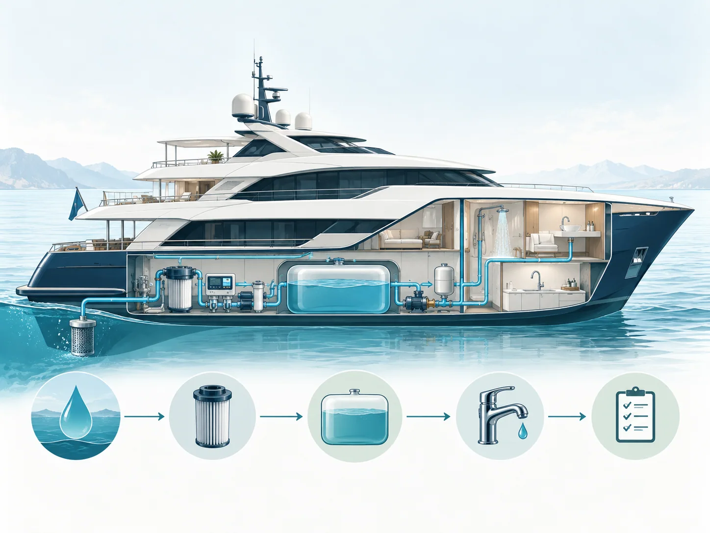
A yacht's drinking water is not a single product. It is a chain of sources, transfers, equipment, tanks and outlets. Every handover creates a potential control point.
Simplified teaching schematic. Follow the configuration, risk assessment and approved procedures for your own vessel.
Explore the source-to-tap controls
Select a section of the water chain to discover what an engineer should verify.
Establish where the water came from, what assurances exist, how it was produced and what initial evidence is available.
A good RO reading — but an unhappy guest
The watermaker product line has consistently low conductivity. A guest reports a persistent unpleasant odour at a single guest bathroom tap. What should the engineer do first?
Educational composite scenario. No identifiable vessel or client information is used.
1.1 Source to tap: map the actual system
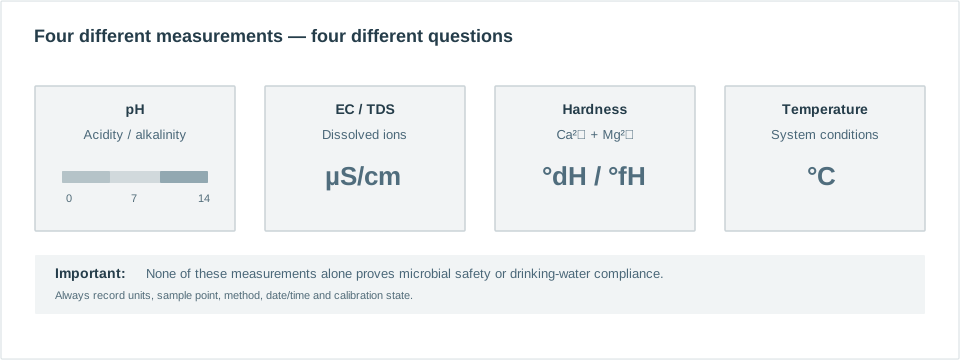
Water may arrive through shore bunkering or be made onboard from seawater using reverse osmosis. The two sources may have very different mineral content, treatment history and microbiological risks. A watermaker product-water meter tells you something about dissolved salts; it does not verify the hygienic condition of the storage tank downstream.
- Source: shore supply or watermaker permeate. Check the source's assurance and any operational records.
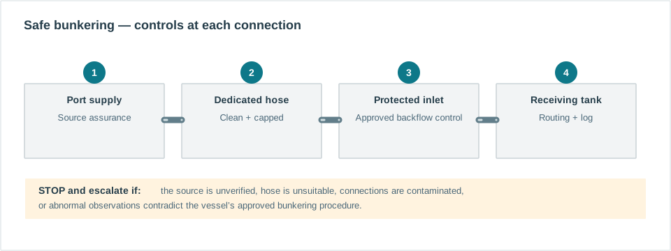
- Transfer: hose, bunkering point, valves and backflow protection. Dirty caps or fittings can defeat an otherwise safe supply.
- Storage: tanks, vents, inspection covers and water age. Tank materials and access arrangements affect hygiene.
- Treatment: filtration, disinfection, conditioning and post-treatment installed in the actual order shown on the vessel drawing.
- Distribution: pumps, calorifiers, return loops, branches, mixers and outlets. Temperature and low-use branches matter.
1.2 Hazard versus control
A hazard is something that can cause harm, such as microbial contamination, chemical contamination or a cross-connection. A control measure is an action or engineering feature that reduces the risk: a protected hose, a verified sampling program, a suitable backflow device or a documented maintenance procedure. A Water Safety Plan identifies both and specifies what to do when a control fails.
| Stage | Example failure | Typical response |
|---|---|---|
| Bunkering | Unknown shore-water quality | Verify documentation; hold transfer if required |
| Tank | Compromised hatch seal | Inspect, isolate if indicated, investigate |
| Outlet | Persistent low use | Apply vessel-approved flushing/monitoring procedure |
1.3 Roles aboard
The master retains overall shipboard authority; the chief engineer typically manages technical systems; deck and interior teams may handle shore connections and report guest complaints. The responsibilities must be written down, including who can stop bunkering, isolate water and inform the master.
A marina says the dock water is drinkable. The engineer still checks the designated hose, valve arrangement, supplier information and tank-routing plan. “Drinkable at the dock” does not equal “verified at every tap”.
Draw the full freshwater pathway on your yacht. Highlight every point where water enters, is stored, treated, sampled or delivered. Record the names of the crew responsible for each stage.
1.4 The two supplies need different verification
Shore water has already passed through an external supplier's system, but the yacht must still control the interface: hose material, coupling hygiene, backflow prevention, receiving tank selection and traceable transfer records. The crew cannot simply assume a port authority's declaration covers the yacht's internal pipework.
A seawater reverse-osmosis (SWRO) plant reduces dissolved salts through a pressure-driven membrane process. Its product is often low in minerals and may require downstream conditioning for taste, corrosion compatibility or process requirements. Its conductivity monitor offers valuable operational evidence, but does not demonstrate that a storage tank or distant shower is microbiologically safe.
1.5 Treat each asset as a possible control point
- Tanks: record material, geometry, access cover, vent protection, inlet/outlet locations, cleaning history and water age.
- Filters: understand whether the purpose is sediment removal, adsorption, softening or another treatment. A filter is not automatically a disinfectant.
- Disinfection: know the chemical or process, monitoring method, validated operating range and points that can lose effective treatment.
- Hot-water systems: understand storage temperatures, circulation, mixing and the possibility of uneven conditions in guest cabins.
- Outlets: know which fixtures are rarely used, which are exposed to guests and which can form aerosols.
1.6 Put a control next to every hazard
For a useful Water Safety Plan, each identified hazard requires evidence of the installed control measure, an assigned owner, a monitoring method, an appropriate action trigger and an agreed response. For example, a compromised tank vent requires an inspection and repair process; merely recording a low TDS reading does not address it. Avoid copying universal limits from another vessel: the applicable requirements and design may differ.
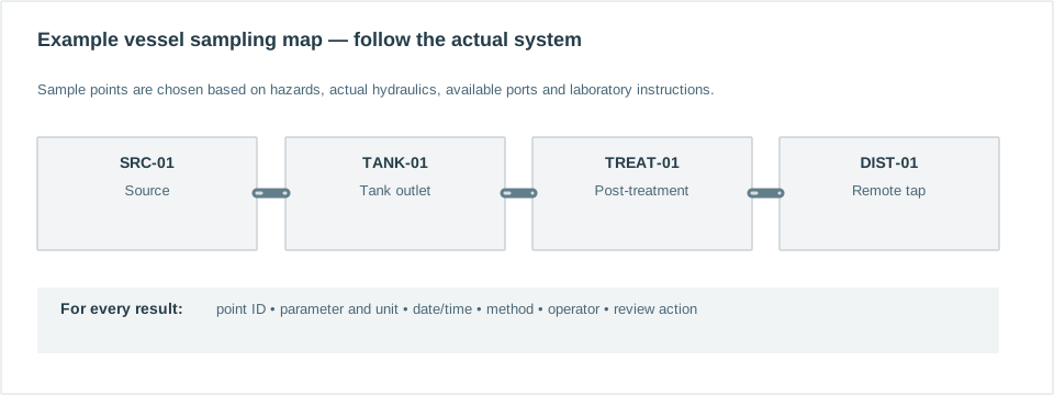
Sketch your actual plant including any bypasses. Add five sample points and annotate three possible pathways that would allow contamination downstream of a correctly functioning watermaker. Ask another crew member to review your drawing.
SYSTEM REFERENCE 01 / STANDARD VESSEL EXAMPLE
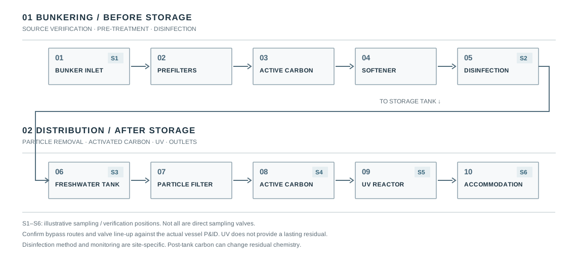
1.7 A two-stage yacht treatment arrangement
A frequently encountered arrangement on larger yachts uses two distinct treatment trains. During shore bunkering the water passes through prefilters, activated carbon, a water softener and a vessel-specific disinfection / treatment stage before entering the freshwater tank (for example silver ionisation, an approved chlorine-based product or an approved peroxide-based product). After storage, the booster/distribution train passes through a particle filter, another activated-carbon filter and a UV unit before supplying accommodation. The flow direction and any bypasses must be confirmed on the vessel drawing.
| Stage | Purpose | What it cannot prove |
|---|---|---|
| Prefiltration | Reduce particulate loading on subsequent units | Microbiological safety |
| Pre-tank carbon | Reduce selected organics, odour and oxidant residual, depending on design | Safe incoming water by itself |
| Softener | Reduce calcium/magnesium hardness by ion exchange | Lower total salinity or sterilisation |
| Disinfection / treatment | Use the actual authorised method and monitor its specific operating parameters | Safety from an ON indicator or generic residual test alone |
| Tank | Store treated water | Protection against later ingress or growth |
| Post-tank particle + carbon | Reduce particles and selected taste/odour contributors | Retention of all disinfectant residuals |
| UV | Inactivate organisms at the UV reactor under validated conditions | Residual protection of distant pipes and taps |
Design principle: a source and tank can be satisfactory while downstream carbon, inadequate UV performance or stagnant pipework still create a problem. Evaluate the whole route, not a single item.
An acceptable shore supply does not eliminate contamination risks during hose connection, transfer, tank storage or distribution. Understand the entire route and its control points.